I2C Bus Lockup Recovery in Production Embedded Systems
How to detect and recover from I2C bus lockups without rebooting.
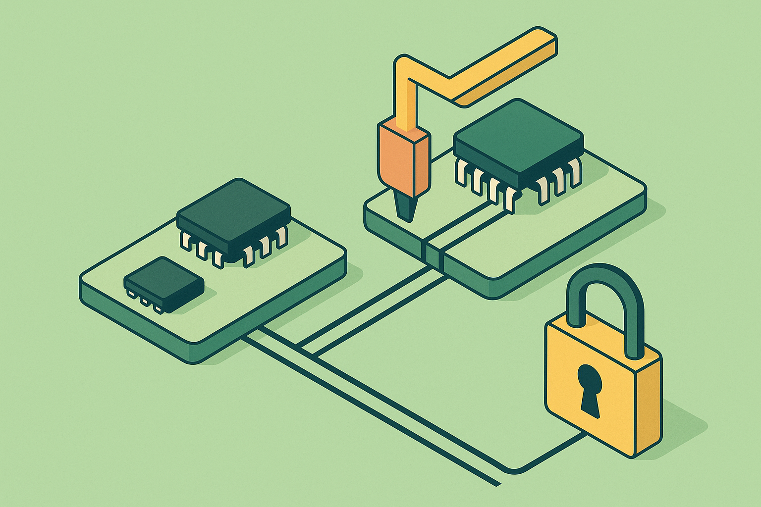
I2C bus lockups are a structural consequence of how the protocol shares a wire, and any production embedded system running I2C long enough, at high enough device count, will eventually hit one. They're a structural consequence of how the protocol shares a wire, and any production embedded system running I2C long enough, at high enough device count, will eventually hit one. The firmware must detect the fault, recover from it deterministically, and keep it from happening again, without a full reboot. It's whether the firmware can detect it, recover from it deterministically, and keep it from happening again, without a full reboot.
The root cause traces back to the bus topology itself. I2C uses open-drain lines with pull-up resistors, a wired-OR arrangement where any device on the bus can pull SDA or SCL low, and no device can force either line high on its own. The bus treats a held-low line as busy, full stop, regardless of which device is holding it or why. Arbitration and clock-stretching are designed to work this way: any device on the bus can pull SDA or SCL low, and no device can force either line high on its own. It's also exactly the mechanism that produces a stuck bus.
Philips developed the protocol and published the first public specification in 1992; NXP inherited it and maintains the spec today (UM10204). It was built for short on-board traces connecting a microcontroller to a handful of low-speed peripherals on a single board, not for the cable runs, connector interfaces, and multi-year field deployments that production hardware actually sees. UM10204 defines speed tiers including Standard-mode (0 to 100 kHz), Fast-mode (0 to 400 kHz), Fast-mode Plus (0 to 1 MHz), and High-speed mode (0 to 3.4 MHz), among others. Lockup risk climbs with every one of those variables, speed, bus capacitance, device count, and all three tend to increase as a product moves from bench prototype to shipping unit. More sensors get added, cable runs get longer, and the clean signal integrity of a dev board disappears.
The distinct failure modes that produce a stuck bus
Two physical scenarios cause a stuck bus, and they matter because the recovery path differs for each. Conflating them is the first mistake most designs make.
Stuck SDA is the more common case. A slave device drives SDA low, typically to ACK a byte on the 8th falling edge of SCL, and then never receives the remaining clock edges it needs to complete the byte and release the line. SDA stays low indefinitely. Depending on how the master's controller is implemented, SCL may get released by the master or may also stay stuck low, but the defining symptom is a slave that's holding SDA and has no path back to releasing it without more clock edges.
Stuck SCL is the harder case to resolve. Here a slave is holding SCL low through indefinite clock-stretching, a legitimate I2C mechanism that's gone wrong; the slave is telling the master "wait," and never stops. This matters for hardware choices too: a device like the TCA4307 bus buffer handles stuck-SDA scenarios well, but indefinite clock-stretching on SCL isn't the same failure mode as the stuck-SCL condition that buffer is built to detect, and the two need different strategies.
A third failure mode is unrelated to the slave. If the master resets mid-transfer, say during a write byte, the slave never receives a STOP condition and has no way of knowing a reset even occurred. The bus comes up stuck on the very next startup attempt. This is especially dangerous during debug sessions: a breakpoint that interrupts an in-flight transaction leaves the bus in exactly this state, and engineers who don't build recovery into firmware from day one often discover this failure mode by hitting it manually in the debugger before a customer ever ships a failing unit.
Noise adds a fourth path to the same outcome. Open-drain lines are exposed to crosstalk and EMI. A false edge on SCL can advance a slave's internal state machine without any corresponding action from the master. Master and slave now disagree about what byte, what bit, and what phase of the transaction they're in, and nothing about the wire itself indicates that anything went wrong.
Finally, there's a purely protocol-level cause: clock-stretching misuse. A slave holds SCL low because the master sent an ACK when it should have sent a NACK after the final data byte, so the slave is still sitting there expecting more data that will never come. The slave holds SCL low because the master sent an ACK when it should have sent a NACK after the final data byte, so the slave is still sitting there expecting more data that will never come, a state mismatch baked into a specific firmware bug. It's a state mismatch baked into a specific firmware bug, and it will reproduce identically on every unit running that code.
Detecting a lockup before it becomes a silent hang
Detection has to start before the first bit goes out, not after something goes wrong. Before issuing a START condition, the master needs to check that both SCL and SDA read high. If either line is already low, the bus is busy, possibly from a prior stuck transaction, and starting a new one on top of that is how one bad transfer becomes a permanent hang.
Timeouts are the second, non-negotiable layer. Every point where firmware waits on a bus event, waiting for the bus to go idle, waiting for an ACK, waiting for a transfer to finish, needs an explicit timeout. An unguarded while-loop polling a GPIO or a status register is the single most common software cause of a permanent hang in the field, and it's avoidable with a few lines of code. The SMBus specification, which builds on I2C, actually formalizes numbers here: any clock cycle held low longer than 25 milliseconds counts as a timeout condition, and a device is expected to reset its communication state no later than 10 milliseconds after detecting that timeout. Those figures, 25 ms and 10 ms, are a reasonable floor even for designs that aren't formally running SMBus.
Once a timeout fires, the master needs to check SCL and SDA individually, because the result determines which recovery path applies. This one check, cheap and fast, is what separates a system that can execute the right recovery procedure from one that's guessing.
Software and hardware watchdogs serve different jobs here and shouldn't be conflated. A software timeout catches the ordinary case: a slave is stuck, but the master's task is still executing and can still run recovery logic. A hardware watchdog is the backstop for when the master task itself has hung despite the timeouts in place, forcing a full device reboot. That reboot works, but it's expensive: in-RAM state, in-progress calibration, and partial telemetry all get lost. A hardware watchdog reboot should be treated as a last resort, not a substitute for a working software recovery path, because a successful bus-clear preserves everything a reboot throws away.
The NXP-specified clock-recovery sequence
NXP's UM10204 spec, revision 7.0, section 3.1.16, lays out the standard bus-clear procedure, and it's been the widely accepted industry approach for bus-clear recovery. It applies specifically to stuck SDA. It does not resolve a stuck-SCL condition caused by indefinite clock-stretching, because the mechanism it relies on requires the master to be able to drive SCL, which isn't possible when a slave is the one holding that line down.
The logic behind the procedure is straightforward: toggling SCL manually pushes the slave's internal state machine forward through whatever byte transfer it's stuck in, one clock edge at a time, until it reaches a point where it releases SDA and is ready to accept a STOP condition.
The sequence runs as follows. First, disable the I2C peripheral so the microcontroller's dedicated hardware isn't fighting the recovery attempt. Second, reconfigure the SDA and SCL pins as plain open-drain GPIOs. Third, drive SCL high. Fourth, check SDA: if it's already high, the bus has cleared and firmware can skip straight to re-enabling the peripheral. Fifth, toggle SCL through one clock pulse, low for roughly 5 microseconds, then high for roughly 5 microseconds, which puts the clock rate at approximately 100 kHz. Sixth, check SDA again: if it's high, issue a STOP condition and re-enable the I2C peripheral. If SDA is still low, repeat the pulse.
The loop runs up to nine times, because nine clock pulses is what it takes to clock a full data byte through a slave device (eight data bits plus the ACK bit). Some implementations extend this to ten pulses for extra margin. If SDA is still low after nine pulses, the bus is genuinely unrecoverable through this method, and firmware needs to escalate, either to a hardware reset path or to reporting an unrecoverable hang up to the application layer, rather than looping indefinitely on a procedure that has already failed.
Hardware provisions that make bus-clear reliable when firmware alone cannot recover
Firmware clock-pulse recovery only works if the physical layer is capable of executing it cleanly. Weak pull-ups, excessive bus capacitance, or the absence of any reset provision can each quietly defeat a software recovery sequence that looks correct on paper.
Pull-up sizing is the first variable, affecting more than steady-state operation. NXP's spec sets a minimum sink current of 3 mA for Standard-mode and Fast-mode, and 20 mA for Fast-mode Plus. Lower resistor values, in the 1 kΩ to 4.7 kΩ range, charge bus capacitance faster and produce cleaner rise times, which matters at higher bus speeds and matters again during a bit-banged recovery sequence, where the GPIO toggling SCL needs a clean, fast edge to actually register as a valid clock pulse to the stuck slave.
Capacitance itself has a hard ceiling: 400 pF total for Standard-mode operation. Each pin on the bus typically contributes something like 5 to 10 pF, and PCB trace capacitance adds more depending on stack-up and trace length. Adding a single one-meter cable out to an external sensor, a common move in a production redesign that a bench prototype never had to account for, can push a design right up against that 400 pF ceiling. A bus already sitting near its capacitance limit with undersized pull-ups will have marginal rise times under normal operation, and the same weak edges that hurt normal transfers can cause the recovery sequence's own clock pulses to miss timing, so the recovery procedure fails from the same electrical cause that produced the bus lockup.
Hardware bus buffers offer a second line of defense that works independently of firmware execution. Texas Instruments' TCA4307 is a hot-swappable I2C buffer built for live-backplane insertion without corrupting data on the bus, and it includes automatic stuck-bus recovery: it watches for SDAOUT or SCLOUT held low for roughly 40 milliseconds and disconnects that bus segment when it detects the condition. It handles stuck-SDA autonomously, and it generates clock pulses on SCLOUT when it detects that line held low, though this addresses a different failure mode than indefinite clock-stretching by a slave. That said, indefinite clock-stretching, where a slave holds SCL low intentionally mid-transfer, isn't the identical failure mode as the stuck-SCL condition the TCA4307 is watching for, and the two call for different handling.
Beyond buffers, a dedicated hardware reset line to each slave, wired to a spare GPIO on the master, gives firmware a way to reset one misbehaving device without power-cycling the entire bus segment and every other device hanging off it.
Structuring the firmware recovery state machine for deterministic, production-safe behavior
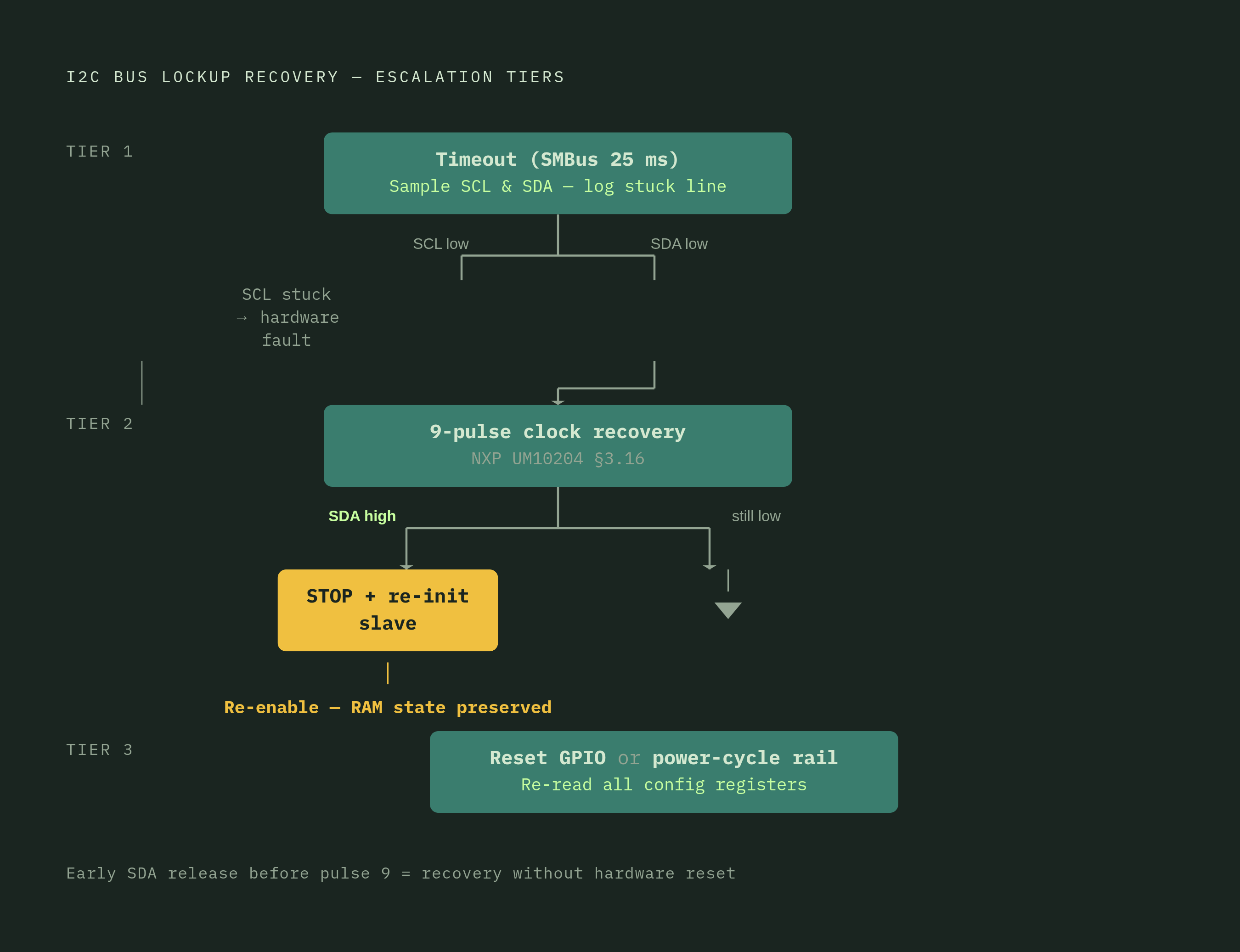
None of the pieces above work as a single retry-and-hope loop. They need to be organized as a tiered state machine, where each tier exhausts its own options before escalating to the next, so the least disruptive fix always runs first and a full reset is genuinely the last resort rather than the default response.
Tier 1 wraps every I2C operation in a timeout, with the SMBus-specified 25 ms clock-low detection threshold serving as a useful reference point, and on timeout samples both SCL and SDA. Firmware should log which line is stuck low and for how long before it decides which recovery path to take next; that decision is what everything downstream depends on.
Tier 2 runs the nine-pulse software clock recovery from UM10204 section 3.1.16, for the stuck-SDA case specifically. If SDA clears at any point before the ninth pulse, firmware issues a STOP condition, re-enables the I2C peripheral, and re-initializes the slave's register state, since the slave's internal state can't be trusted to have survived the recovery cleanly. If SDA is still low after all nine pulses, firmware logs the sequence as unrecoverable through clock pulsing and escalates to Tier 3.
Tier 3 is the hardware reset path. If the slave has a dedicated reset GPIO, firmware asserts it directly. If no reset GPIO exists but the bus segment sits behind a controllable power switch, firmware toggles that rail instead. Either way, once the reset completes, firmware has to treat every piece of slave state as unknown: configuration registers get re-read from scratch, and nothing about the device's prior state is assumed to have persisted through the reset.
That layering, timeout, then clock recovery, then hardware reset, is what makes bus recovery deterministic rather than a hopeful retry wrapped around a five-second delay. A production system that runs I2C for years across thousands of units doesn't get to treat a lockup as a one-off anomaly. It has to treat it as an expected event with a known, tested response, because sooner or later, on some unit, it's going to happen.
Sources
- spellfoundry.com
- I²C Bus Lockup: Causes and Recovery Methods
- I2C lock-up: prevention and recovery - Pebble Bay
- nxp.com
- totalphase.com
- TMS320F28034: Possible cause(s) of I2C bus hang-up
- [Solved] STM32F4 I2C Master Clock Stretching Fail | Community
- Preventing and Recovering I2C Bus Lockups: Best Practices for Embedded Systems